
 EN
EN
 AR
AR
 FR
FR
 DE
DE
 IT
IT
 JA
JA
 KO
KO
 PT
PT
 RU
RU
 ES
ES

Qual é o princípio de funcionamento de um sensor indutivo de proximidade?
Como Funciona um Sensor de Proximidade Indutivo?
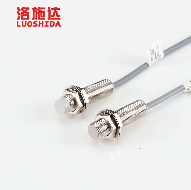
Se você já foi a uma fábrica ou viu uma linha de produção em funcionamento, pode ter notado pequenos dispositivos retangulares posicionados próximos a esteiras transportadoras ou braços robóticos. Esses são sensores de proximidade: o sensor de proximidade indutivo é um dos tipos mais comuns. Mas você sabe o que é realmente um sensor de proximidade indutivo? É mais simples do que imagina! Vamos analisar o sensor passo a passo, para que você entenda o que o torna uma excelente ferramenta para detectar objetos metálicos.
Os sensores indutivos de proximidade operam sem necessidade de luz, som ou contato ativo. Eles simplesmente automatizam a detecção por meio da indução eletromagnética, um princípio que já resistiu ao teste do tempo. Esses sensores determinam com confiabilidade a presença de metais ao executar várias tarefas de automação industrial. Evitam colisões de robôs quando braços são movimentados próximos a peças metálicas, e classificam e contam produtos metálicos em esteiras transportadoras. Para apreciar o valor desses sensores na automação industrial, é importante compreender os fundamentos dos sensores, a engenharia e a física envolvidas, e como eles convertem alterações em um campo magnético em sinais utilizáveis.
Componentes Principais Que Tornam Isso Possível
O princípio de funcionamento depende das várias partes de um sensor de proximidade indutivo. É um sistema de várias partes que precisam funcionar em uníssono. Para apreciar o sistema, considere o fato de que existem quatro elementos fundamentais que cada sensor tem. Estas partes fundamentais precisam cooperar para que o sensor funcione.
O primeiro componente é o oscilador. Considere isto como a fonte de energia do campo magnético do sensor. Produz uma corrente alternada de alta frequência —normalmente na faixa de kilohertz —e a direcção da corrente oscila rapidamente. A seguir segue a bobina de detecção, que é normalmente um laço de fio fino e de alta qualidade (por exemplo, cobre) enrolado em torno de um núcleo de ferrita. Quando o oscilador envia corrente alternada através da bobina, a bobina desempenha uma função significativa: gera um campo magnético alternado em torno de si. É como uma pequena "bolha" invisível de magnetismo que circunda a face frontal do sensor.
A próxima etapa é o projeto do circuito amplificador. A função desta peça é "ouvir" as alterações no campo magnético. Quando algo perturba esse campo, o que veremos em breve o que é esse "algo", as propriedades elétricas da bobina também mudam —e essas mudanças são pequenas. O amplificador aumenta essas pequenas variações para torná-las mais fortes, permitindo que a próxima etapa as processe. A última parte é o circuito de saída. Quando o sinal amplificado chega a esta parte, o circuito determina se há um objeto metálico presente e envia um sinal, normalmente digital (ligado/desligado), para a máquina com a qual está interligado, instruindo um transportador a parar, um braço robótico a se mover ou um contador a incrementar seu valor em um.
A Chenwei Automation projetou os componentes principais com que os sensores de proximidade indutivos são construídos de forma otimizada. Por exemplo, a bobina de detecção é fabricada com fios de cobre de qualidade para proporcionar uma detecção constante e precisa. O sensor não funcionaria se algum desses componentes estivesse ausente, e isso é válido para todos eles. Eles estão alinhados com o restante dos sistemas.
Indução Eletromagnética: Os Fundamentos
Depois de abordarmos os componentes, vamos analisar o componente principal que faz tudo funcionar: a indução eletromagnética. Esse conceito foi desenvolvido por um cientista inglês, Michael Faraday, no século XIX, e é o princípio por trás do funcionamento de geradores e transformadores. Analisaremos seu princípio de funcionamento no contexto dos sensores de proximidade indutivos.
A bobina de detecção recebe corrente alternada de alta frequência. Quando a corrente é aplicada em uma direção e depois na direção oposta, a bobina gera campos magnéticos alternados. Esta é a "bolha" magnética "invisível" que se estende do sensor de proximidade até os 30 mm em seu ponto mais distante quando o sensor está ativado. Quando o sensor não está ativado, o campo está em repouso e constante. A ausência de um campo magnético indica que há um objeto metálico próximo ao sensor. Nesse estado, o oscilador está ativo, a impedância da bobina é constante e não há flutuações.
É aqui que a lei de Faraday da indução eletromagnética é útil. Quando um condutor, que é um metal, é exposto a um campo magnético, nele fluirá uma corrente devido à variação do campo magnético. Essa corrente é uma corrente parasita, que é uma corrente que flui em um padrão espiral e circula sobre si mesma. Imagine como a água gira em uma poça com redemoinhos. Elas terão seu próprio campo magnético e apresentarão polaridade oposta àquela produzida na bobina do sensor. Esta é a lei de Lenz e parte da eletrodinâmica. Agora, em vez de um campo magnético constante, a bobina terá um campo magnético de "reação" produzido pela corrente parasita.
Alterações no campo magnético oposto influenciam o funcionamento da bobina de detecção. Você se lembra da definição de impedância da bobina? Quando o campo magnético oposto interage com a bobina, a impedância aumenta. Torna-se mais difícil para a bobina acomodar a corrente alternada enviada pelo oscilador, e o oscilador pode enfraquecer ou desacelerar devido à resistência adicional. Esse fenômeno —um aumento na impedância ou uma diminuição na saída do oscilador —é [provavelmente] a única coisa que o circuito amplificador do sensor registra. É bastante razoável concluir que o sensor está indicando: "Há um objeto metálico presente!"
Como Detecta Objetos Metálicos (O Truque Principal)
Estabelecemos que o sensor de objetos metálicos detecta a corrente e interrompe o campo magnético do sensor. Como o sensor traduz essa interrupção e sinaliza ao controlador para indicar "objeto presente" e "objeto não presente"? Essa é a função da restante circuitaria e a razão pela qual os sensores de proximidade indutivos são confiáveis para uso na indústria. Vamos analisar um exemplo. Imagine um dispositivo sobre uma esteira transportadora que move porcas metálicas. Se uma porca não está próxima ao sensor, o campo magnético ao redor da porca não se distorce. A impedância da bobina permanece baixa, a intensidade operacional do oscilador permanece alta, e o amplificador não registra alterações significativas. O circuito de saída mantém o estado "normal", e o sistema envia um sinal "baixo" para o sistema da esteira, indicando que esta deve continuar em movimento.
Uma porca metálica desliza sob o sensor, entrando em seu alcance de detecção. Correntes parasitas são induzidas na porca, gerando um campo magnético oposto. A impedância da bobina muda e a corrente do oscilador diminui. O amplificador detecta a mudança na corrente (ou a diminuição da impedância) e a amplifica. Esse sinal ampliado é enviado ao circuito de saída, que é configurado com um "limiar". Esta é uma linha que, quando ultrapassada, inicia uma ação. O limiar é ultrapassado e o estado do circuito de saída muda: ele envia um sinal "alto" para o sistema de controle. Esse sinal pode instruir o transportador a pausar por um momento para que um braço robótico possa pegar a porca, ou pode incrementar um contador que acompanha as porcas processadas.
Aqui está algo que você precisa saber: sensores de proximidade indutivos detectam apenas certos materiais —e isso é principalmente metais como aço, alumínio e cobre. Eles não detectam não-metais como plástico, madeira ou vidro, já que esses materiais são condutores fracos. Em muitas fábricas, no entanto, isso é uma grande vantagem. Por exemplo, se você estiver embalando peças metálicas em sacos plásticos (que são não metálicos), o sensor pode ignorar o saco e detectar apenas o metal. Os sensores de proximidade indutivos da Chenwei Automation são particularmente bons nisso. Eles conseguem distinguir até mesmo objetos metálicos e não metálicos posicionados próximos, evitando assim interrupções na produção por sinais falsos.
Outra coisa a entender é que o tipo e o tamanho do metal afetam o alcance de detecção. Uma grande chapa de aço, por exemplo, será detectada a uma distância maior do que um pequeno parafuso de alumínio, já que superfícies metálicas maiores produzem correntes parasitas mais intensas. No entanto, isso raramente é um problema. A maioria dos sensores industriais é projetada para funcionar com diversos tipos de metais, portanto você não precisará trocar os sensores toda vez que mudar a peça que deseja detectar.
Lógica Prática de Funcionamento em Cenários Industriais
É importante entender como os diferentes componentes funcionam no contexto científico, a fim de obter uma visão geral da lógica por trás das diversas aplicações industriais em uma planta de produção. Utilizaremos algumas ilustrações para demonstrar o princípio de funcionamento. Isso explica a popularidade dos sensores indutivos de proximidade no campo da automação.
Vamos usar um fabricante de peças automotivas como exemplo. Pode haver um sensor de proximidade indutivo fabricado pela Chenwei Automation utilizado em uma linha de montagem que prende parafusos metálicos aos blocos do motor. O sensor está no braço robótico que segura o parafuso. Antes de o braço se mover para aparafusar o parafuso ao bloco do motor, o sensor precisa confirmar que o braço realmente está segurando um parafuso. Se o braço estiver vazio, ele apenas perderá tempo girando ou possivelmente danificará o bloco do motor. Veja o que acontece: quando o braço pega um parafuso, o parafuso passa a estar dentro do alcance de detecção do sensor. Correntes parasitas se formam no parafuso, a impedância da bobina muda e o sensor envia um sinal de "parafuso presente" ao controlador do robô. O controlador então ordena ao braço que se mova até o bloco do motor e inicie o processo de aperto. Se não houver parafuso, o sensor envia um sinal de "sem parafuso" e o controlador detém o braço, evitando assim um erro.
Outro exemplo seria uma linha de embalagem para latas de metal. As latas são transportadas por um sistema de esteira e precisam ser enchidas com refrigerante e seladas. Um sensor de proximidade indutivo é fixado próximo ao bico de enchimento. Quando uma lata se posiciona sob o bico de enchimento, o sensor identifica a estrutura metálica da lata e aciona o sistema de enchimento. À medida que a lata é preenchida, o sensor detecta a ausência da lata e sinaliza ao bico de enchimento para parar. Este sistema é projetado para detectar as latas e reabastecer, garantindo que nenhum refrigerante seja desperdiçado, mesmo durante produção em alta velocidade.
Mais uma vez, o tempo de resposta necessário do sistema sensorial está na faixa de milissegundos. Isso é crucial para manter as taxas de produção desejadas. Se o sistema sensorial demorasse até mesmo um segundo para responder, isso sinalizaria uma falha no processo produtivo. Para combater esses problemas, a Chenwei Automation projeta seus sensores para responderem em tempo real ao movimento de sistemas robóticos de alta velocidade e transportadores. A maioria das tecnologias sensoriais pode ser afetada em ambientes empoeirados, mas os sensores indutivos de proximidade não. Eles toleram sujeira e umidade e continuam operando em condições adversas. Os sensores só deixam de funcionar quando os campos magnéticos interagem dentro do sensor, desativando-o.
Outra coisa que vale a pena mencionar é que esses sensores são "sem contato". Isso significa que eles conseguem detectar um objeto metálico sem precisar tocá-lo. Essa é uma vantagem em relação aos interruptores mecânicos, cujas partes móveis entram em contato e se desgastam com o tempo. Os sensores indutivos de proximidade não tocam em nada, razão pela qual podem durar por um número maior de anos e exigem muito pouca manutenção. Isso é importante para fábricas que operam 24/7, pois permite maior tempo de atividade e reduz os custos com substituições.